
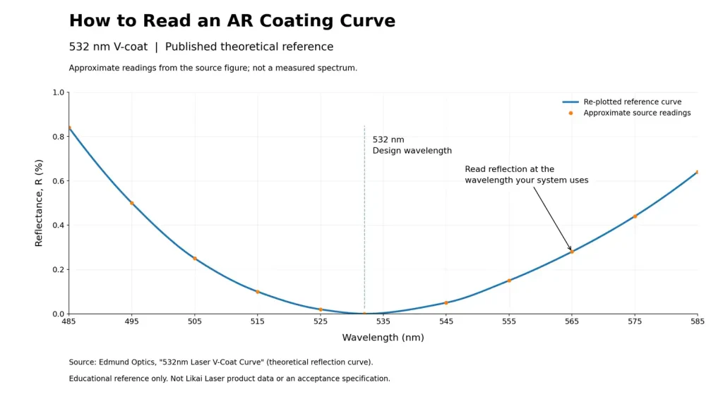
Read an anti-reflection (AR) coating curve by locating the operating wavelength or band, checking whether the vertical axis shows reflectance or transmission, and matching the stated angle of incidence and polarization to the optical system. Then check whether the specification applies to one surface or the complete optic. A laser-line coating suits a defined narrow wavelength requirement; broadband AR covers a wider band. The lowest point on a graph alone is not enough to select either one.
Start With the Axes and the Working Wavelength
The horizontal axis usually shows wavelength in nanometers (nm) or micrometers (µm). The vertical axis may show reflectance, R, or transmission, T, often as a percentage. On a reflectance plot, a lower curve means less reflected light under the stated conditions. On a transmission plot, a higher curve means more transmitted light. Confirm the label before interpreting a peak or dip.
Locate the wavelengths that the component actually needs to transmit. A low reflection value elsewhere on the graph does not answer that requirement. For a camera lens, review the relevant imaging band; for a laser optic, identify the actual laser wavelength and any additional wavelengths that must pass through the same component.
Choose Laser-Line or Broadband AR for the Application
A laser-line AR coating is optimized around a specified design wavelength. A V-coat shows a narrow dip in its reflectance curve near that wavelength. It can be appropriate for a stable, narrow-line laser, but low reflection at the design wavelength does not establish performance across an imaging band. Broadband anti-reflection (BBAR) coatings reduce reflection over a wider wavelength interval, making them useful for optics carrying a broader spectrum. Edmund Optics’ AR coating guide explains this distinction.
For example, a component transmitting one fixed laser line and a lens used with broadband visible illumination have different selection priorities. The first needs the required performance at that line; the second needs suitable performance across its imaging band. A system using two laser wavelengths needs both checked explicitly. It may call for a multi-line coating or a suitable broadband design. SCHOTT’s optical coating technical details distinguish V-shape, broadband, laser-line and multi-line AR designs.
Separate Average Reflectance From a Wavelength Limit
An average reflectance value, often written Ravg, summarizes performance over a defined band. It does not mean that reflection stays below that number at every wavelength. A limit at one laser wavelength, an average across a band and a maximum across that band are different acceptance requirements.
Compare supplier data on the same basis. If a detector depends on one part of a broad band, inspect that region rather than relying only on the average. Check whether the plotted line is a calculated design, a typical curve or a measurement supplied for the order. Agree which numerical limits govern acceptance; a representative curve should not silently become a guaranteed specification.
Check One Surface Versus the Complete Optic
A reflectance curve for one coated surface is not a transmission curve for a complete lens or window. Light encounters more than one interface, and the substrate can absorb light. Confirm which faces are coated and whether the reported transmission includes the substrate and both faces. For assemblies, establish which optical elements are included in the measurement.
Subtracting a single-surface reflection percentage from 100% does not establish the finished component’s transmission. Absorption and scattering also need consideration. Material transmission is a separate part of window selection, as described in Edmund Optics’ explanation of optical windows. For the manufacturing implications of the substrate itself, see our guide to optical coating for glass, plastic and metal substrates.
Match the Angle of Incidence and Polarization
Angle of incidence (AOI) is measured from the surface normal: 0° means light reaches the surface perpendicularly. A curve specified at 0° should not be assumed to describe a tilted optic. The spectral response and residual reflection can change with angle. At oblique incidence, s- and p-polarized light can also have different responses. The s electric field is perpendicular to the plane of incidence; the p electric field lies within it.
Check the legend for AOI and polarization, including whether a line represents s, p or unpolarized light. For a converging beam, consider the range of angles reaching the surface, not just the central ray. Edmund Optics’ introduction to optical coatings explains why coating performance depends on the intended angle and polarization.
What an AR Coating Curve Does Not Establish
A spectral curve describes reflection or transmission under its stated conditions. It does not, by itself, establish laser-induced damage threshold (LIDT), resistance to cleaning, environmental durability or surface quality. For a processing laser, assess the operating power or pulse conditions and the relevant damage-test conditions separately. Absorption sites can cause local heating even when reflection is low, as discussed in Edmund Optics’ technical note on high-power optical coatings.
These distinctions explain why a coating suitable for a camera lens cannot be assumed suitable for a laser cutting optic. Our article on optical coating applications puts the different system functions in context.
Discussing a Coating Requirement With Likai Laser
Likai Laser supplies standard optical products and evaluates custom optical manufacturing and coating requirements. The optical lenses and coating services shown on our website provide a starting point for that discussion. The industry examples above explain selection principles; they are not numerical performance claims for Likai Laser products.
When discussing a curve, identify the wavelength or band, required reflection or transmission limits, substrate, coated faces, AOI and polarization. If a parameter is unknown, mark it for review. Share any existing curve with its labels and conditions intact so the coating requirement can be evaluated against the intended application.